The first stage of designing a lightning protection facility is to determine its level. There are four levels (effectiveness) of lightning protection:
- Level I (98% effectiveness),
- Level II (95% effectiveness),
- Level III (90% effectiveness),
- Level IV (80% effectiveness).
The method of determining this level is given in the PN-EN 62305-2 standard Lightning protection – Part 2: Risk management, as well as in the NF C 17-102 (2011-09) standard.
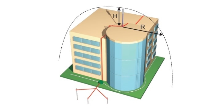
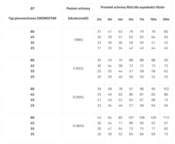
According to the NF C 17-102 (2011-09) standard, the protection radius R of the GROMOSTAR lightning rod is related to the timing advance value ΔT, protection levels I, II, III, IV and the height H of the GROMOSTAR lightning rod. The height value H is equal to the height difference between the lightning conductor blade and the highest point of the protected building, minimum 2m.
ΔT - the difference expressed in microseconds between the moments when a bottom-up leader develops on a PDA lightning rod and the moments when a bottom-up leader develops on a traditional lightning rod measured in the laboratory under the conditions specified in the NF C 17-102 (2011-09) standard.
|
ΔT
GROMOSTAR lightning rod type
|
Protection level(effectiveness) |
Protection radius R (m) for height H (m) |
| 2m |
3m |
4m |
5m |
7m |
10m |
20m |
60
45
35
25 |
I (98%) |
31
26
23
17 |
47
39
30
25 |
63
51
36
34 |
79
63
49
42 |
79
63
50
43 |
79
64
51
44 |
80
65
52
45 |
60
45
35
25 |
II (95%) |
35
30
25
20 |
53
44
35
29 |
70
58
44
40 |
88
72
57
50 |
88
72
58
50 |
88
73
58
52 |
90
75
62
55 |
60
45
35
25 |
III (90%) |
39
33
27
23 |
58
49
40
34 |
78
65
52
46 |
97
80
65
57 |
98
81
67
58 |
99
83
68
63 |
102
86
73
65 |
60
45
35
25 |
IV (80%) |
43
36
30
26 |
64
54
47
39 |
85
71
64
52 |
107
89
73
65 |
108
90
75
66 |
109
92
77
69 |
113
97
82
75 |
For buildings requiring 1++ (99.9%) protection and for buildings posing an environmental threat (hazard factor h = 20, EN 62305-2) or which may cause environmental pollution (hazard factor h = 50, EN 62305-2), the radius values should be reduced by 40%.
According to the NF C 17-102 (2011-09) standard:
- A lightning conductor with early leader emission should be installed in the highest place of the building. It should be the peak of the protected zone.
- The lightning conductor tip should be located at least 2 m above the protected area including antennas, air conditioners, superstructures, etc.
- Each lightning conductor should be connected to at least two discharge wires.
- For better distribution of lightning current, both ground discharge routes should be located on different building facades.
- When using a high voltage insulated cable, one route can be made from the lightning conductor to the ground
- If there are several lightning conductors in the building, discharge cables can be used together.
- The route of the discharge cables should be as straight as possible and as short as possible without sharp angles.
- Antenna masts on the roof should be connected to the lightning protection system (connection by means of a spark gap), unless the antenna's distance from the lightning protection system meets the separation distance requirements.
- The earth resistance value should be as low as possible (R≤10 Ω).
- The lightning protection system should be connected to the building earth electrode.
- The lightning discharge recorder should be installed on the shortest, most accessible discharge line above the control connector.
- To ensure surge protection, it is advisable to use appropriate internal protection (surge arresters).
- The GROMOSTAR lightning rod can be installed on a free-standing mast to secure open areas with low-altitude facilities (parking lots, gas stations, sports grounds, swimming pools, etc.)
The rules listed above are general, therefore it is recommended to consult our technical department. In order to avoid errors and thus create a threat to people and property, it is recommended to entrust the execution of the design and installation of a lightning protection to specialists.